 There’s nothing quite like a boat for testing an electrical circuit to its limits! At the best of times the cables and terminals must put up with a combination of the omnipresent salt atmosphere and vibration (the United States Coast Guard requires fuel tanks to be tested at up to 25 G’s); at the worst of times these cables may be totally submerged in bilge water, or dripping with engine oil, or cooked at high temperatures. All too often, salt infiltrates terminals and wicks up conductors, causing corrosion and electrical resistance; vibration causes copper conductors to work harder and fracture; and oil and high temperatures degrade insulating properties, leading to short circuits. As electrical efficiency declines, equipment fails, and in worst cases fires are started.
It makes no sense to install high-quality, marine-rated electrical and electronic equipment on boats without at the same time using high quality, marine-rated cables and terminals to power the equipment. In the marine environment, “high-quality, marine-rated” is determined by the following:
- Tinned conductors, in which every strand of a cable is individually tinned to minimize corrosion.
- Multi-stranded conductors, which use what is known as Type 3 stranding to maximize flexibility and minimize the potential for work hardening and fracture.
- Heavy-duty, moisture- and oil-resistant, high-heat rated PVC insulation.
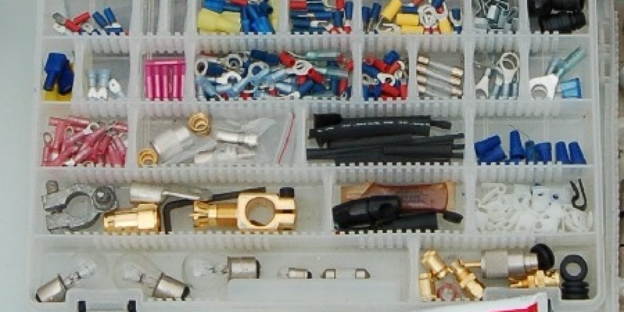
- Tin-plated, annealed copper terminals with a rugged nylon insulator designed to be double crimped so as to relieve vibration-induced stresses at the crimp;
- Heavy-wall, glue-lined, heat-shrink tubing to seal connectors against salt intrusion.
Ancor cables, terminals, and heat-shrink tubing are claimed to be built to meet these demanding standards. Properly installed, they will ensure the integrity of electrical circuits for many, many years to come.
Cable Sizing
Proper installation is primarily a matter of sizing a cable to match its tasks, using the correct tools to attach terminals, and providing adequate overcurrent protection with fuses and circuit breakers.
Cable sizing is simple enough. It is a function of the length of a cable (measuring from the power source to the appliance and back), and the current (amperage) that will flow through it. This can be found by checking the label on the appliance in the circuit, or the specifications sheet for the appliance. The longer the cable, or the higher the amperage, the bigger the cable must be to avoid unacceptable voltage losses. And there should always be plenty of extra margin for safety because an appliance may actually use more current than what it is rated for because of heat, low voltage, extra load and other factors.
F or 12-volt circuits, the relationship between cable length, current flow, and cable size is given in the two tables below. Note that Table 1 presupposes a 3% voltage loss in the cable, while Table 2 presupposes a 10% voltage loss. What this means is that when the circuit is fully loaded (i.e. operating at rated amperage), the voltage at the appliance will be 3% or 10% below that at the battery. For example, if the battery is at 12.6 volts, the appliance will be seeing 12.2 volts (3% loss), or 11.34 volts (10% loss).
The cable sizing tables are used by running across the top row until the column with the relevant amperage is found, and then moving down the left-hand column until the row with the relevant distance is reached. The number in the body of the table at the intersection of this row and column is the wire size (in something known as the American Wire Gauge); the lower the number, the bigger the cable! Use this wire size (gauge) to find the correct product. But don’t hesitate to go to a heavier (fatter) wire than the table indicates.
Many appliances (notably lights) will run fine with a 10% voltage loss, but others are particularly sensitive to such losses (notably charging circuits, and some electric motors). In general, given the harsh realities of the marine environment, it’s better to use the 3% volt drop table when sizing cables, rather than the 10% table. There’s never a performance penalty if a cable is marginally oversized; there is always a performance penalty (and possibly a safety hazard) if it’s undersized. ABYC and the United States Coast Guard require a not to exceed 3% drop for circuits involving the safety of the vessel or its passengers and in other cases.
The ground (negative) cable is as much a part of a circuit as the positive cable; it must be sized the same. In general, each appliance should be supplied from the distribution panel with its own positive and negative cables, although lighting circuits sometimes use common supply and ground cables to feed a number of lights (in which case the supply cables must be sized for the total load of all the lights).
Continue reading – http://www.boatus.com/boattech/articles/electrical-wiring-on-boats.asp
The post BoatUS Boating Tip – Electrical Wiring On Boats appeared first on ODU Magazine-North America's #1 Digital Fishing Magazine.